Analyze - Classiq Visualization Tool
Once a quantum algorithm was designed and a quantum program was synthesized, the next natural thing one would to do is to analyze the quantum program and to check if the underlying quantum circuit implements the desired quantum algorithm properly and how. This can be done with the Classiq visualization tool that enables exploring the quantum circuit interactively on different level of functional hierarchies, as well as to extract crucial information about it.
The Classiq visualization tool can be accessed in 3 different ways:
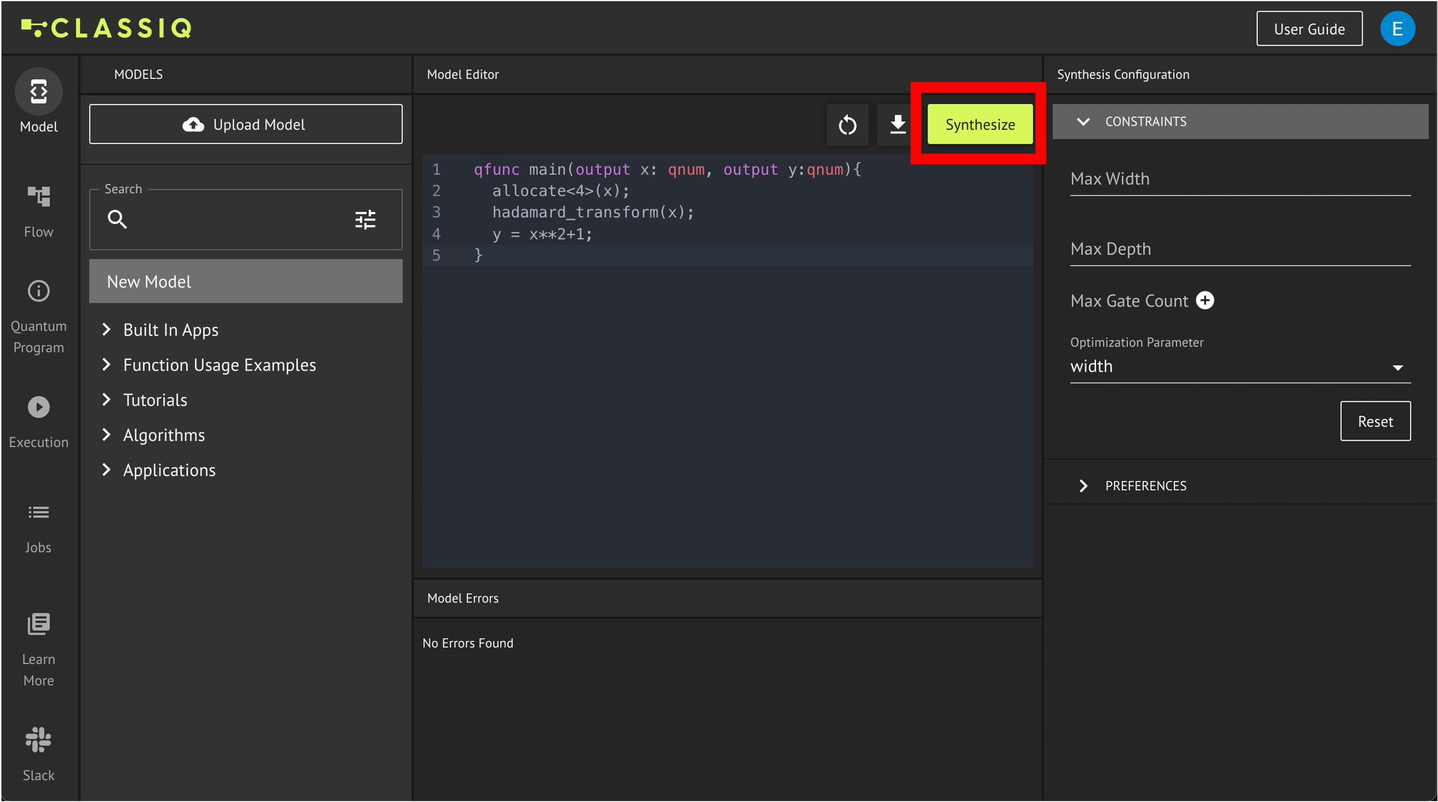
1.From the IDE - from the Model tab, by pressing the Synthesize button:
2.From the Python SDK - by running the show(quantum_program) command in the Python SDK:
from classiq import *


@qfunc
def main(x: Output[QNum], y: Output[QNum]):

    allocate(4, x)
    hadamard_transform(x)  # creates a uniform superposition
    y |= x**2 + 1


quantum_program = synthesize(create_model(main))
show(quantum_program)
Opening: https://platform.classiq.io/circuit/f729dc29-9aa2-49f6-907f-c284445c4dc8?version=0.41.0.dev39%2B79c8fd0855
qfunc main(output x: qnum, output y: qnum) {
  allocate<4>(x);
  hadamard_transform(x);
  y = (x ** 2) + 1;
}
3.Directly Uploading a circuit/ quantum program to the IDE:
In the following, we cover some key aspects of the visualization tool. For a full list of all the features and possibilities of the tool access the reference manual.
Navigating
The high-level functional design approach of Classiq enables analyzing quantum circuits on different level of functionalities. You can view your circuit only on the functional building blocks level, e.g. hadamard_transform and Arithmetic in the example below, or you can zoom in to the actual gate-level implementations:

In addition to the plus and minus buttons, you can also use the navigation map button to navigate through your circuit:
This is especially helpful in large circuits.
Quantum Program Information
On the left-hand side of the visualization tool, you can find information about the quantum program such as the circuit depth, circuit width and the gate count. As you can see in the picture below, it is divided into information about the quantum program the the transpiled quantum circuit:
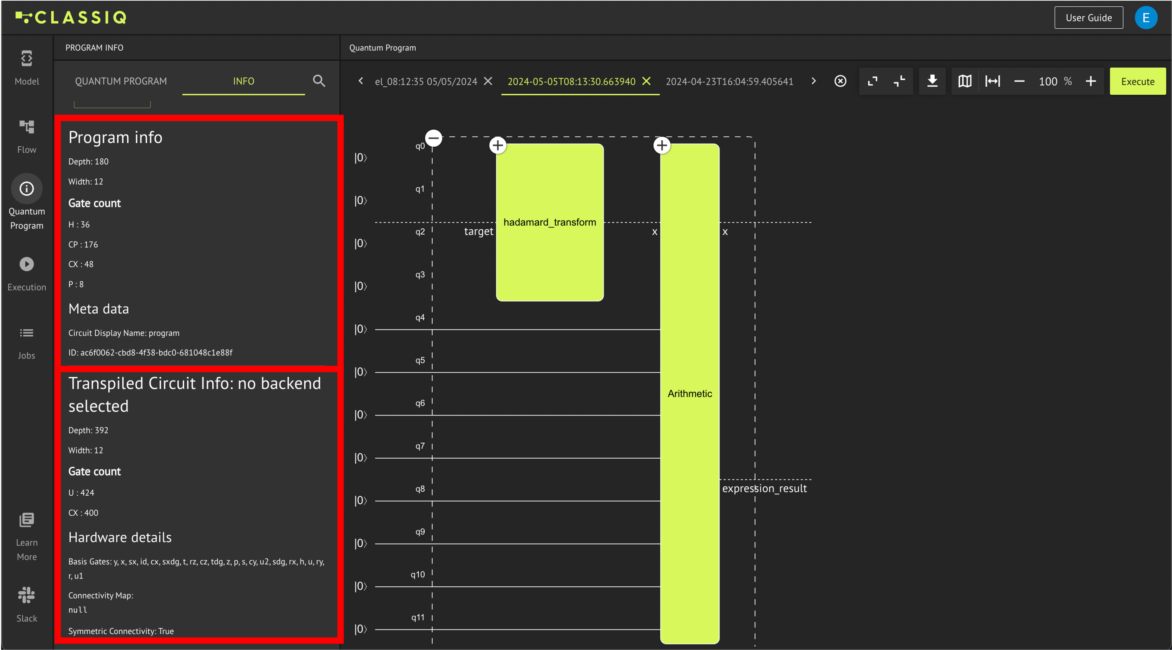
The quantum program is the output of the synthesis engine and it contains the circuit implementation that preserves the functional logic of your algorithm. This is the information which correlates to the circuit which is viewed on the center of the page. E.g. in the example covered in this tutorial, the final functional building block within the Power block and the first functional building block within the Adder block should cancel each other as applying them consecutively is equivalent to not applying them at all (these blocks are the quantum Fourier transform and its inverse which cancel each other when applied consecutively):
On the other hand, the transpiled circuit is the circuit that is sent for execution which is further optimized by eliminating functional blocks that have no influence on the circuit like the two blocks that cancel each other. The transpiled circuit contains only the set of gates defined by the optimization preferences. It is possible to view the transpiled circuit by downloading the circuit as Transpiled QASM and uploading it to the visualization tool:
The Quantum program can be downloaded in various formats including QASM, JPEG, JSON, and LaTeX code. To do this, click the download button as illustrated in the preceding image
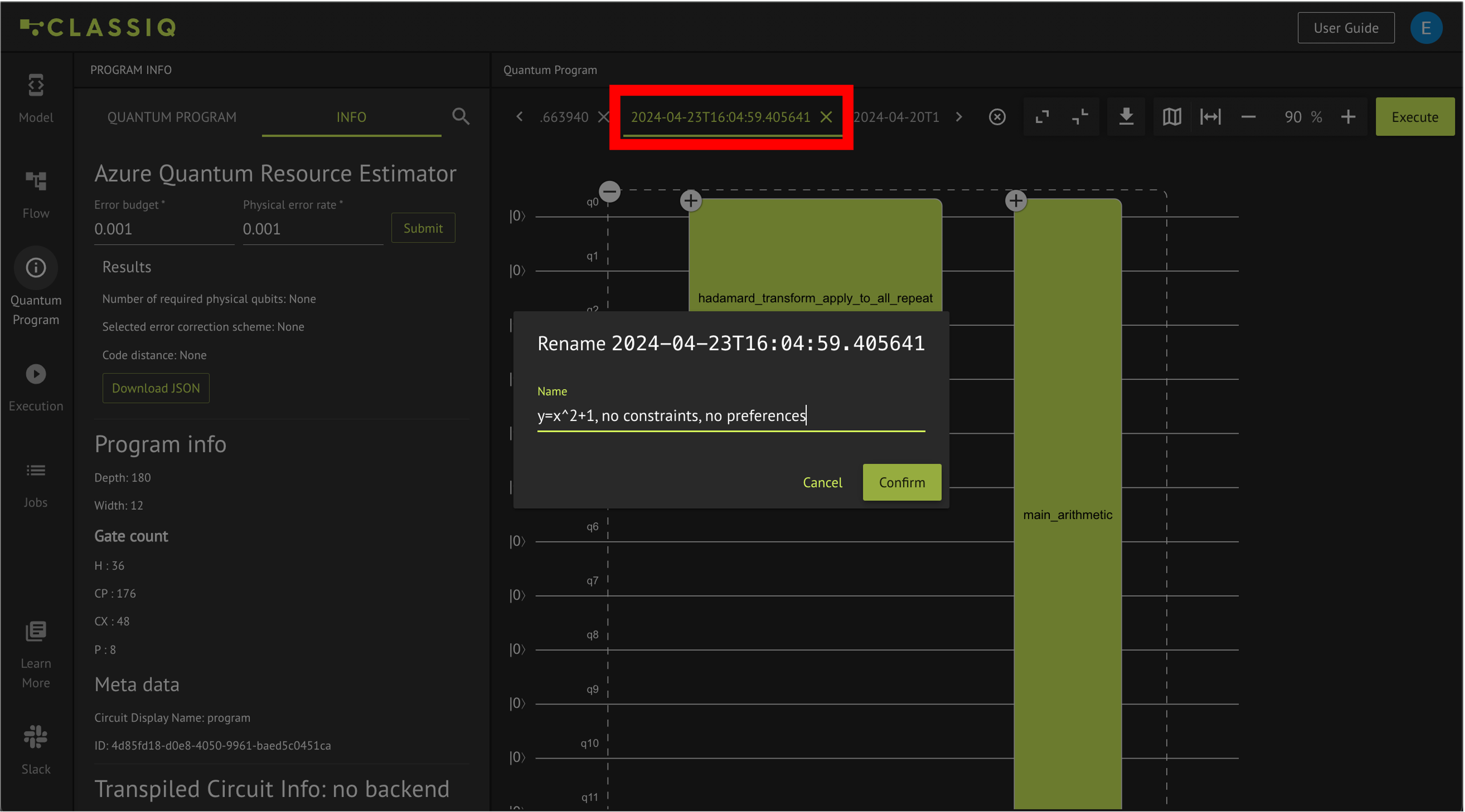
Adapting Names
In order to keep track of your quantum circuits when you are working, it is recommended to rename them with some indicative names. The renaming is done by double clicking on the circuit tab, entering the new name and confirming.
By double clicking on the blocks within the circuit, their names can be adapted as well.
After analyzing the quantum circuit one would usually want to either adapt the model or to execute the circuit on a simulator or on real hardware. Continue to Execute chapter to understand how to do that.
Verify Your Understanding - Recommended Exercise
Open the above example in the IDE and from the Quantum Program tab, export the circuit as a LaTeX file. View it in a LaTeX Editor (it is recommended to use Overleaf - a free, easy to use online LaTeX editor).
write_qmod(create_model(main), "analyze")